All posts by audiodane

Scale Cutout Revealed

Would an actual-size, scale-model cutout of the PMCv1 excite anyone?

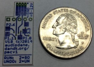
PMCv1B_scalecutout

The design was created using EAGLE, an amazingly affordable Schematic and PCB layout tool that I’ve been using since 2006. I printed out both front and back sides “actual size,” then cut them out and taped them together.  The image above shows the bottom side of the unit. As you can see, the PMCv1 is a little taller but narrower than a US quarter.  In more technical terms, it’s 1.15″ high x 0.500″ wide.  Not shown is the connector and its five (5) wires that will actually connect to the TV.

Production Programming Header Ordered

I placed an order tonight for a card-edge connector (for the curious, I’m using this little guy) that should connect to the thin card edge traces (aka “fingers”) near the top edge of the board in the above photo. It should be here in about two days, and I’ll use it to “test-fit” with the scale cutout in the photo. This is going to be the “mass” programming header (quick, easy, no-solder) for the PMCv1 units. This is the last check before placing the order for the first 100 PMCv1 units. If it fits, then I’ll start placing orders for boards, parts, 3 types of TV connectors, heat-shrink tubing, shipping envelopes, and mailing labels!

Pre-order Status

As soon as I get all the parts ordered, I’ll start working on the PayPal pre-order page.  That activity should start sometime next week. I don’t know yet how pre-orders will even work– I need to research that on PayPal and see what options exist. I don’t know if a pre-order will charge you at the time of pre-order placement, or at the time of order fulfillment.  But whatever it is, I will be sure to make it very clear on the ordering page.

Expected Availability

To keep costs low, I am opting for the absolute slowest production speed; that means it will take about 6-weeks for the first 100 PMCv1’s to be produced. Slow, but affordable. If all goes well, first units for sale will be ready about 2-weeks after that.  So, roughly 8-weeks from today.  During the 6-week production time, I will prepare the software for the new custom PMCv1 hardware, as well as prepare the custom programming header.

More next week!
..dane

Whew, finally a chance to breath!

My apologies to everyone who has been wondering if I fell off the face of the Earth. I had a really big project come through at work but it had huge amounts of tasks in only a 4-6 week window.  I was working all sorts of crazy hours trying to get it all done. The project went well, I think the customer is happy (so far), and it looks like I’m still employed for a the foreseeable future.  All those are good things.  However PMCv1 didn’t get any attention during that time, which is bad.  The silver lining to more PMCv1 delays is that I caught a bug in the PMCv1 hardware that needed to be fixed before production, and last night I finally had time to fix it.

Moving Forward..

So we had a 4-6 week delay in the project due to work, but I’m ready to move forward again now. The board problem has been fixed, and I also found a simpler way to program the boards in quantity which will really help. Because it’s been over 30 days, I have to get the suppliers to refresh their quotes, but a refresh shouldn’t take but a couple of days so it should go fairly quickly.  I am looking to finalize everything any place the order for 100pcs of PMCv1 hardware in the next week or so!

cheers,
..dane

Preliminary PMCv1 Pricing

This is going to be a bittersweet update for many of you.  The good news is that PMCv1 is nearing production!  The bad news is that I have not yet been able to get quotes to support my initial pricing goals, so the price of these first PMCv1 units has gone up, as I feared in an update earlier this year.  This is why it has been three weeks since my last update; I have been trying to find ways to reduce the cost.  This update reports where I’m at today, and my plan moving forward.

Why The Cost Increase?

Since I began the PMCv1 several months ago, I have had a great many people contact me from around the globe expressing their interest in the PMCv1.  While such international interest is exciting, it didn’t take me long to realize that my initial plans to build a few, by myself, by hand, just wasn’t going to cut it.  I already have a 9-5 day job, and just don’t have the free time to be soldering PMCv1 boards together every night! I will need to go straight to the custom board design even for the first units.

So immediately the cost went way up.  My initial hopes to have someone build a couple dozen units was going to cost me some 6 times more than my original price target!  So I went back and asked for quotes of higher quantities..  Pushing my initial order from 30pcs to 100pcs dropped the per-piece price tremendously, but it is still going to cost me twice my original price target.. boo.  At the end of the day, if my cost doubles, I have to pass that along.  Likewise if my cost drops in the future, I can pass that along too.  If I had enough capital to purchase 300-500 units in the first run, maybe that would have hit my initial price target.  I just don’t have that much money to spend up-front.

Preliminary Pricing

This pricing information is still preliminary.  I am still waiting for two last quotes to be updated.  There is a chance that one of these quotes will drop the price of the PMCv1.  If not, however, then the numbers in my spreadsheet are pretty clear.

Preliminary PMCv1 is USD$60/each.  Shipping to USA will remain free (USPS Flat Rate Padded Envelope).  International shipping is TBD.

Preliminary Availability

I hope to have the last two quotes returned back to me this week.  My original plan was to spend February getting cost estimates so that I can move forward. That is largely on-track.  So the plan continues to be that near the end of February, I’ll finalize all my costs and place the first order of 100 PMCv1 units.

The first PMCv1 units will then arrive some 4-6 weeks after I place the order, during which time I will be working on a PMCv1 test fixture.  Since I’ll have so many of them now, I need a way to test them quickly and reliably. I cannot afford to sell PMCv1’s that don’t work!  And 100pcs is far too many to be plugging in to the back of my TV.  So I’m going to adapt one PMCv1 unit with some custom software to test all the other units.  This one unit will act like a Panasonic Plasma television to each unit, and will pretend to be a TV turning on and off, with various different values “in memory” to properly test the functionality of the PMCv1 modules, including the “undo” switch and LEDs — cool, huh?

The first PMCv1 should ship in April.

Purchasing Method (USA)

I will be opening a PayPal Business account to handle PMCv1 sales.  The preliminary pricing above is based upon a direct purchase using a “Buy Now” button on this website.

PMCv1 ordering should open in March.

Purchasing Method (International)

I am considering using eBay’s International Shipping Program for international sales. The up-side to this approach is that it becomes MUCH easier for me to get these units shipped around the world without having to know all the details about each country’s customs and import laws.  The downside to this approach is that as with production costs, every dollar more that it costs me, I have to pass along to the buyer.  eBay charges 10% final value fee plus whatever their international shipping program costs.  So eBay customers will have to pay about $6-10 extra to handle the additional fees.

If any of you have any other ideas for international customers, please let me know!

What’s Next?

From here the plan is simple:

  • Pray for a miracle on the last two outstanding quotes
  • Finalize the total cost spreadsheet for a 100-piece order
  • Place order for 100 PMCv1 units (ouch!)
  • Setup PayPal Business account
  • Start working on a custom PMCv1 “Test Fixture” to test each unit before it ships

Stay warm,
..dane
Let the Quoting Begin

I finished the small 1/2″ x 1″ PMCv1 board late last night.  Yay!  Now I get to package it up and send it to Advanced Circuits (and probably a few other places) to get manufacturing quotes.  I’ll need to refresh the connector pigtail quotes as well.  I still have to work out a plan for assembly (easy), and a plan for testing final built-up units (not so easy), but this is all very good news.

So When Can I Buy?

Give me a couple weeks into February to get the quote process underway.  If all goes well, I’ll have final purchase price and availability information by the end of February.

What About Pre-orders?

I have not yet decided about pre-orders.  I have heard too many horror stories about people paying for goods before they’re ready and for this reason or that, end up very unhappy in the end.  Pre-orders greatly help me offset the initial production cost, but I’m hesitant to be bound to that in case something in the first production round goes south and I am unable to deliver as I had hoped.

What Will it Look Like?

Well, small.  About a half-inch by one-inch.  With a pigtail cable sticking out one side, and two switches and LEDs (one red, one green) sticking out the other..  With some heat-shrink around the electronics to ensure that once tucked into your TV, nothing will short-circuit.  When I actually have one made, I’ll of course furnish pictures.  Until then, get a ruler out and draw that 1/2″ x 1″ rectangle.  . . .  Small, huh?

That’s all for this week.
..dane

Mid-January Update

I have been amazed at how many different people have been contacting me lately, from all around the world.  Thank you for your continued interest in PMCv1!  Last week I was on a business trip and got to fiddle around with the custom PCB designs again.  One question that I came up with was whether or not I could include a few other useful features and sell a version of PMCv1 without any software (and without the costly TV connector) on it as a small development board (for hobbyists like myself).  This would allow me to further offset costs of PMCv1 production and scrap the current “existing board” design altogether.

Why Scrap the Existing Design?

There are a couple good reasons, that I’ve mentioned in previous posts.  First and foremost, the existing small PCB that I purchased to do my initial development and testing with is lacking a protection diode.  Second, it is lacking the “undo” switch.  Third, it only has one LED.  None of those in themselves are deal-breakers.  But combined, it means I’ve got to do a fair amount of work to the little guy to get it ready to go.. on each and every board bought.  Ugh.

The smallest custom board that I’ve got mostly done includes two LEDs, two switches, a protection diode, and a voltage regulator (for 5V support).  The idea here is that I can have them produced in quantities of 100 at a time, and all I really need to do is program the chip, solder on the TV connector, add some protective shrink-wrap, and ship it out the door.  Those are all much more reasonable steps, and the time savings are significant.  It also greatly reduces the likelihood of simple human errors since the final assembly steps are easier and not as delicate.  And two LEDs are far easier to understand than one.  Especially when one’s red and one’s green!

What’s in a Hobby Board?

That’s a tough question.  I’ve recently been picking the brains of some really talented folks about some features that I would think “pretty cool” to add to the design to make it a hobby board that people might actually want to buy.  They’ve had some really great ideas, too.  Some of them are clearly outside the time-frame that I’d like to see, but some may be possible.  In the end, I’m going to have to make some compromises.  So it’s likely not going to be a full-fledged hobby board.  But maybe some will still want to buy it?

Okay, So What Now?

The rest of the night I’m going to be trying to wrap up the little custom PCB and get it ready to be quoted by my good friends at Advanced Circuits. I have used them for many years across several day-jobs and they have always done a really fantastic job.  Super quality, Super price, Super speed, Super everything.  There are cheaper fab houses out there, but sometimes you get what you pay for when you go with the lowest bidder.  I know what I can expect out of Advanced Circuits, and they’ve done a great job to earn my business.  Maybe by next week I’ll have better information on cost and availability estimates.

A Quick Note About “Rising Blacks” versus “Floating Blacks”

A few emails have come across my inbox asking if “Rising Blacks” and “Floating Blacks” are the same thing.  Unfortunately, they’re NOT the same thing.  PMCv1 is intended to reset the Minimum Luminance Level, or MLL, or “Black Level” of the Panasonic Plasma TV.   Over time, these models exhibit several steps of increased black levels over their lifespan.  This is the “Rising Blacks” problem.  Day one sees the darkest darks in movie shadows possible by your particular model.  At various times through its life those darks become a little lighter color…not so dark. This problem is what PMCv1 sets out so solve.

“Floating Blacks” is an entirely different problem that some Panasonic Plasma sets exhibit.  Floating blacks are where the TV dynamically adjusts its black level based on average picture content.  So, in a really dark scene, the overall “black” level is reduced, to make the image that much more inky black.  In bright outdoor scenes, where such an inky black isn’t necessary, the darkest dark isn’t quite so dark.  The problems can arise when there’s just the right amount of content on the screen where the TV can’t quite make up its mind and the darkest shadows in the picture step back and forth between inky and grey, inky and grey, etc.

PMCv1 is intended to correct the “Rising Blacks,” but at this time cannot do anything for “Floating Blacks.”

PMCv1 2014 New Years Update

It’s been over two months since my last update, and I apologize for that.  As I knew would happen, the holidays took our family by storm an we were busy from early November through New Years.  As many of you know, I was trying to get the whole project done before Halloween for that reason.  Oh well, hobby projects always take the brunt of scheduling conflicts, and here we are.

I have worked out a few hours a week through January to spend on PMCv1 and we’ll see where that gets us.  First up was to pour through service manuals and extract connector information (for both 11pin and 20pin connectors), part numbers, and net names, and try to generate a spreadsheet that captures my findings.  I have that largely finished now, with the service manuals that I have received.  I cannot guarantee the list is 100% perfect, but I’ve been through it several times and haven’t found any errors (yet).

PMCv1 Availability List Updated

The PMCv1 Availability page has been updated (today) with my latest findings.  Many models are now listed in one of several categories, which I’ll describe below:

  • Yes (3V, Tested) — this means the board runs on 3V (yay!), and has been tested to work properly..  Lowest risk category
  • Yes (3V, Un-tested) — this means the board runs on 3V (yay!), but has not yet been tested.  I only have one Panasonic television, so cannot test all other models. However, as units are tested on customer sets and I receive feedback, I will move them to a “User Tested” category.
  • Planned (5V) — this means that an adaptation will have to be made for the board to run on 5V (boo), but that service manual schematics seem to indicate that no additional changes or testing will be required.  When 5V support is complete, I will convert these to “Yes (5V, Un-tested).”
  • Hopeful (5V) — this means that an adaptation will have to be made for the board to run on 5V (boo), and that there are other differences in the service manual schematics that give me reason to suspect more adaptations will be required.
  • Don’t Know Yet — this means I have not yet been able to determine if support will be possible through the current PMCv1 module architecture, for reasons that vary model-to-model.

What’s Next

That’s a good question, thanks for asking.  With a decent sized list of TV models that are expected to work, the question becomes pragmatic.  I can go ahead and possibly build a small number of PMCv1 modules, see how they sell and perform, and if things go well then proceed with a custom design to support 5V models and investigate the “Hopeful” categories.  There are several other options available, but this one seems like the easiest to achieve with my limited resources.  There are some concessions that will have to be made however, such as no protection diode.  This simply means that I will need to provide orientation instructions, because if it’s plugged in backwards it might fry the module (because I’m using existing, not custom, parts).  I have so-far been unsuccessful in plugging the module in backwards, but I wouldn’t put it past a stubborn heavy hand to force it in the wrong way.

The other approach is to wait and go with a custom board (that I talked about in previous updates), of which I have two designs mostly complete.  These designs will include protection diodes, but will cost more and take more time.  Also it’s a much larger up-front investment on my part, which I’m not yet sure I can recover.

I am leaning towards the existing design (with no logging options, but with the “undo” switch that I have talked about before), because it’s simpler and costs less money to get started.  That way I can see how the module works with several different models and it will give me the time I need to determine whether or not there is enough interest to pursue a custom design and 5V model support.

That’s all for now.  Thanks for your time!
..dane

PMCv1 development parts on their way..

I have put in the order for the microprocesor eval kit, a couple small target boards, and a couple I2C EEPROM chips.  The I2C chips I was able to request free samples (we’ll see if they honor the request), but I had to throw down about $40 for the microprocessor evaluation boards. I also have 3-each of both A17 and A18 pigtail connectors.

All of this, plus a few wires and some soldering, is all I’ll need to get started. I have some reviewing to do of Miro’s website as well as some other posts throughout the avsforum thread, but I’m very excited to get started on this little widget!

If you haven’t already, please take a moment to fill out my feedback request form, and let me know what model TV you have, and which connectors are present under it’s service connector tab.  I’m trying to get as much information as possible about which models have which connectors, so that I can do the most good for the most people, with the least risk.

thanks!
..dane

Panasonic MLL Reset Widget Pre-Design Feedback Request

I’m working on a little widget that plugs into the back of a Panasonic plasma television to periodically reset the minimum luminance level (MLL, aka “black level”) to its fresh, out-of-box, initial state. Theoretically this will apply to 11th gen (e.g. ), 12th gen (e.g. tc-p50g10), and 13th gen (e.g. ) model families. Maybe others, I don’t know. I am simply applying what I have read in the avsforum thread to a tiny, easy-to-install module. Specifically, I am building directly upon mironto’s site that details a DIY approach using an Arduino board. Miro, in turn, based his work off users clktmr and markone, also members of avsforum. Their work, in turn, was based on earlier effort to understand the why’s and how’s of the rising black levels in the first place. Without clktmr, markone, and mironto’s (and so many others’) previous works, this project would never exist. I’m simply taking all of their previous combined effort and packaging it into a self-contained widget that plugs in the back of the TV.  Much more information and background can be gathered by reading Orta’s initial post in the avsforum thread.

I’m going to call it PMCv1 (Panasonic Plasma MLL Clearer, version 1). Inventive, huh?

But there are several paths available for this solution, and I need some input.. If you would be so kind as to fill out and submit the form below, it would be a huge help.. Name and email is not strictly required, but I assure you that I won’t be giving that information out anywhere. It would simply help me get back in touch with you if I had additional questions..

Here are the answers that I have received so far (this is manually generated from the emails that I have received, I will update the graph several times per week during this feedback request period)..


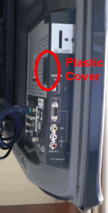
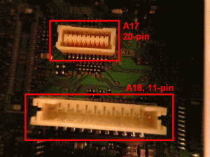
I would appreciate as much feedback as possible, during this design phase! I expect this phase to last just a couple weeks.. The two pictures below should help with connector identification. Your TV may have the plastic service port tab in a different location, the example below was taken from the tc-p50g10 model.

BackOfTV-side_sm_labeled
(side of tc-p50g10, your model may be different)

BackOfTV_sm_labeled
(underneath plastic access cover of tc-p50g10)


Thanks for your feedback!
..dane


Feedback Form:
(The feedback period has ended)